A chain is a device for taking linear measurements in the field. Chain surveying is accomplished by taking linear measurements only.
26.1.1 Basic principle of chain surveying
The principles followed in chain surveying are:
- The whole of the area to be surveyed is divided into a skeleton of framework consisting of a number of well connected networks of ‘well conditioned’ triangles.
- The details are to be located with respect to the sides of the triangles or any other subsidiary lines running between the sides by taking lateral measurements called ‘offsets’.
26.1.2 Skeleton framework for chain surveying
To decide on the best planning of the skeleton framework for chain surveying a field, one should base his judgment on the minimum labour to produce a map with the required details and minimum distortion. The following points should be taken care of:
- Through reconnaissance it should be ascertained that due to the presence of thick hedges, trees or any other obstacles, there should not be any obstruction to the laying of chain along the framework, taking the necessary measurements and the intervisibility along the lines of the framework.
- Preferably a long line should run through the centre of the area to form a base line on which well-conditioned triangles should be based. The base line should prevent the relative rotation of the triangles due to error in the measurements when they are plotted in the map. This arrangement for the framework will limit the distortion in the map to a minimum.
- The lines should run closer to the details, which are to be described with respect to them by taking lateral measurements called ‘offsets’.
- To avoid long offsets additional lines should run between the sides of the triangles of the framework.
- There should also be some other additional lines for checking the accuracy of the measurements.
- Care should be taken so that no portion of the framework goes beyond the boundary of the area to be surveyed.
26.1.3 Terms used in chain surveying
- Main station: Main station is a point in chain survey where the two sides of a traverse or triangles meet. These stations command the boundaries of the survey and are designated by capital letters such as A, B and C.
- Tie stations or subsidiary stations: Tie station is a station on a survey line joining main stations. These are helpful in locating the interior details of the area to be surveyed and are designated by small letters such as a, b and c.
- Main survey line: The chain line joining two main survey stations is called a main survey line. In Figure 26.1, AC represents a main survey line.
- Tie line or subsidiary line: A chain line joining two tie stations is called a tie line, such as jk. It is also called an auxiliary line. These are provided to locate the interior details, which are far away from the main lines.
- Base lines: It is the longest main survey line on a fairly level ground and passes through the centre of the area. It is the most important line as the direction of all other survey lines are fixed with respect to this line.
- Check lines: Check line or proof line is a line which is provided to check the accuracy of the fieldwork. The measured length of the check line and the computed one (scaled off the plan) must be the same.
- Offset: It is the distance of the object from the survey line. It may be perpendicular or oblique.
- Chainage: It is the distance of a well-defined point from the starting point. In chain surveying it is normally referred to as the distance of the foot of the offset from the starting point on the chain line.
26.1.4 Field work in chain survey
Suppose a plan is required for a small area as shown in Figure 26.1. The surveyor should first of all examine the ground to ascertain as to how the work can be arranged in the best possible manner. This is known as reconnaissance survey. In this process, the surveyor selects suitable ground points to be used as stations like A, B, C, etc.
Stations are arranged so that the entire area may be controlled from these points and all the main survey lines AB, BC, CD, etc. run near to the boundaries. The survey lines should not be many and lie over flat level grounds as far as possible. The triangles formed by survey lines should be well conditioned.
The main survey lines are measured with a chain and offsets are taken to the boundaries. Offsets are taken wherever there is a bend or any special feature in the boundary. In cases, where the boundary forms a smooth curve offsets are taken at the end of each chain. Offsets should be short, particularly for locating important details.
The lengths and positions of offsets being known, the boundaries can be plotted to their shapes. The other details which are deep inside the area, such as a well as shown in Figure 26.1, can be located by selecting tie stations, drawing tie lines and taking offsets to the ground features.

Figure 26.1 The main survey line and tie lines in chain surveying
26.1.5 A survey chain
Gunter, revenue, engineer and metric chains are the various types of chains, which are normally used for surveying. The chains are mostly divided into 100 links. While gunter’s chain is 66 ft long, the revenue chain is 33 ft long and the engineer’s chain is 100 ft long. Metric chains are either 30 m or 20 m in length.
The different parts of a chain are shown in Figure 26.2. The part marked 1 is a brass handle which contains a semicircular groove at its end for accommodating arrows during chaining. Parts marked 2 and 3 are the collar and eye bolt. 2 and 3 form a swivel joint with the brass handle. Part 4 is a circular ring which connects the end link marked 5 with the eye bolt. The links are connected with each other with three circular rings marked 6.
All links except the end links are of equal lengths. The link length measures the distance between the centres of the central rings of the joints on either side of the link. The end link forms the complete link length with the brass handle. The end link length measures the distance from the end of the handle to the centre of the central ring of the joint next to the end link. The length, of course, is to be measured while the chain is held straight.
The swivel joint allows rotation of the handle preventing the deformation due to twist in the end link. The three-ring joints provide enough flexibility to prevent the deformation of the links by bending.
For the ease of readability of the chain, different brass tag marks or tally marks are provided in it at definite length intervals, identical tags being placed at identical distances from the either end of the chain. This provides an opportunity to read the length on the chain at any of its points from either of its ends (marked 8 in Figure 26.2).
All links are made out of SWG No.8–No.12 wires of galvanized mild steel, in accordance with IS:1492-1970, having a diameter of 4 mm usually. The material is sufficiently soft and ductile to withstand hammering when the bent links are to be rectified. It may be noted that a chain with 100 links will have 99 joints between the links and two joints between the handles and the end links. There are 4 × 101 = 404 pairs of wearing surfaces at those joints.

Figure 26.2 Components of a chain
26.1.6 Folding and unfolding chain
Unless great care is taken in folding and unfolding a chain, the links of the chain may bend and the rings of the joints may be deformed, making the length of the chain different from its standard length. This will introduce error in the measurements when employed in survey. Moreover, the chain cannot be boxed without folding it in a proper way.
Before putting it to use the chain bunch is taken out and held in one hand. The rest of the bunch is to be spread on the ground. One of the handles is to be released now and the chain is to be dragged when it is unfolded.
After its use, the chain is to be folded before it is put into its box. The central ring at the middle of the chain or the tally mark there and both the handles of the chain are put together at one end and the central rings quarter length, that is between 25th and 26th links and at 3 quarter length, that is between 75th and 76th links are put together at the other end. The chain laid and folded in this way on the ground will have bunches of 4 links lying side by side along the length. Each bunch of four is to be held and folded over to the next bunch alternatively to complete the folding of the chain.
26.1.7 Tapes
Tapes are available in a variety of materials, lengths and weights. The different types of tape in general use are explained below (Figure 26.3).
- Cloth or linen tape: These are closely woven linen or synthetic material and are varnished to resist the moisture. These are available in 10–30 m in length and 12 to 15 mm in width. The disadvantages of such tapes are that it is affected by moisture and gets shrunk, its length gets altered by stretching and it is likely to twist and does not remain straight in strong winds.
- Metallic tapes: It is a linen tape with brass or copper wires woven into it longitudinally to reduce stretching. As it is varnished, the wires are not visible. These are available in 20–30 m length. It is an accurate measurement device and is commonly used for measuring offsets. As it is reinforced with wires, all the defects of linen tapes are overcome.
- Steel tapes: These are 1–50 m in length and 6–10 mm in width. At the end of the tape a brass ring is attached, the outer end of which is the zero point of the tape. Steel tapes cannot be used in grounds with vegetation and weeds.
 Figure 26.3 Types of tapes
 - Invar tape: This is made of an alloy of nickel (36 per cent) and steel having a very low coefficient of thermal expansion (0.122 × 10⁻⁶/°C). These are available in lengths of 30, 50 and 100 m and in a width of 6 mm. The advantages and disadvantages of an invar tape are as follows.
26.1.7.1 Advantages
- Highly precise.
- It is less effective by temperature changes when compared to other tapes.
26.1.7.2 Disadvantages
- It requires much attention in handling.
- It is soft and so deforms easily.
PVC coated fibre glass tapes are most common nowadays, as they are more durable and weatherproof.
26.1.8 Marking station points on the ground in chain surveying
On a normal ground, the station points are to be marked by driving wooden pegs into the ground. Made of hard wood the wooden pegs are 25 mm × 25 mm in cross section and 150 mm in length. When driven, at least 50 mm should be above the ground.
26.1.8.1 Accessories used
- Ranging rod: 2-3 m in length, with well-seasoned timber made into a rod of 30 mm diameter, alternatively painted red and white or black and white over a length interval of 200 mm. The ranging rod is provided with an iron shoe at its bottom and carries a 250 mm × 250 mm flag coloured red and white or yellow and white to make it conspicuous from a distance. It is used to find out the points lying on a line, i.e., in ranging a line. It is also used to mark the station points when the wooden pegs driven for the purpose are not visible from a working distance (Figure 26.4).
 Figure 26.4 Ranging rods
 - Ranging poles: These are ranging rods with longer lengths varying from 4 to 6 m. These is employed to range long lines on undulatory grounds.
- Offset rods: It is almost the same as the ranging rod with the only difference that here the flag at the top is replaced by a stout ring or a hook for pulling or pushing the chain. It is employed to take short offsets in ordinary works.
- Arrows: Accompanying each chain are 10 arrows. They are also called marking chains or pins and are used to mark the end of each chain during the process of chaining (Figure 26.5).
- Pegs: Wooden pegs are used to mark the positions of the stations. They are made of hard timber and are tapered at one end. They are usually 2.5 cm2 and 15 cm long. But in soft grounds, pegs 40–60 cm long and 4-5 cm2 are suitable (Figure 26.6).
- Cross staff: The cross staff is used for finding the foot of the perpendicular from a given point of a line and for setting out a right angle at a given point of a line. There are three forms of cross staff, namely the open cross staff, the French and the adjustable cross staff (Figure 26.7).
- Open cross staff: The simplest form of the cross staff is the open cross staff. It consists of the head and the leg. The head is simply a wooden block octagonal or round around 15 cm side or diameter and 4 cm deep.To find the foot of the perpendicular from a given point to a given chain line, i.e., to take the offset, the cross staff is planted or held vertically on the chain line where the offset is likely to occur and turned until one pair of opposite slits is directed to a ranging rod at the forward end of the chain line. Looking through the other pair of slits, it is seen if the point to which the offset is to be taken is bisected. If not, the cross staff is moved forward or backward on the chain line until the line of sight through the pair of slits at right angles to the chain line bisects the point.
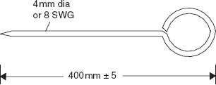 Figure 26.5 Arrow
  Figure 26.6 Peg
  Figure 26.7 Different types of cross staff
 - French cross staff: It consists of an octagonal brass tube with slits on all eight sides. The base carries a socket so that it may be fitted on the pointed staff when the instrument is to be used. The sights being too close, it is inferior to the open type.
- Adjustable cross staff: This may be used for setting out angles of any magnitude. However, the results are only approximate owing to the closeness of the sights.
- Open cross staff: The simplest form of the cross staff is the open cross staff. It consists of the head and the leg. The head is simply a wooden block octagonal or round around 15 cm side or diameter and 4 cm deep.To find the foot of the perpendicular from a given point to a given chain line, i.e., to take the offset, the cross staff is planted or held vertically on the chain line where the offset is likely to occur and turned until one pair of opposite slits is directed to a ranging rod at the forward end of the chain line. Looking through the other pair of slits, it is seen if the point to which the offset is to be taken is bisected. If not, the cross staff is moved forward or backward on the chain line until the line of sight through the pair of slits at right angles to the chain line bisects the point.
26.1.8.2 Ranging a line – direct and indirect
Ranging a line means establishing intermediate points on the line. This may be accomplished with visual observations and ranging rods, looking through an instrument called ‘line ranger’ or looking through theodolite in precision works for ranging long lines. The operation may be classified as follows:
- Direct ranging
- Indirect ranging
- Direct Ranging: In direct ranging, the surveyor can observe and direct the person holding the ranging rod to put the ranging rod at any intermediate point on the line being ranged out.
- Indirect Ranging: Here, the surveyor cannot find out any intermediate points on the line on his own and has to depend upon the statement of a person at the end of the line and also on the statement of the person carrying the ranging rod.
26.1.8.3 Ranging with ranging rods
In Figure 26.8, A and B are two station points. The line AC is to be ranged. At A and C two ranging rods are to be driven vertically. The verticality of the rods is to be assured with the help of a plumb bob. If the rods at A and C are truly vertical, the surveyor standing about 2 m behind A and looking along the line AC will find the vertical projection of the rod at C hiding behind the vertical projection of the rod at A, as shown in the figure. If the surveyor stands very near to A he may miss the vision for comparison. The surveyor will now send a man with a ranging rod to stand on the line AC at a distance less than one chain length from A. The surveyor should advise the man through hand signals to put a rod vertically on the line AC till he finds with his one eye closed and looking along AC the vertical projections of both the rods hiding behind that of the rod at A. The point B will then lie on AC. This way the other points may be ranged out.

Figure 26.8 Ranging a line
26.1.8.4 Code of signals in ranging
In the field nothing should be communicated through loud speaking because it will lead to exhaustion. The following hand signals are therefore to be followed during the ranging of a line
- The rapid sweeping movement of the right hand should mean long movement to the right. The slow sweeping movement of the right hand should mean very short movement to the right.
- Similarly, the rapid sweeping movement of the left hand should mean long movement to the left and the slow sweeping movement of the left hand should mean short movement to the left.
- The right or the left arm extended should mean to continue moving to the right or left accordingly.
- The right arm up and moved to the right should mean to make the rod vertical by moving the top of the rod to the right. Similarly the left arm up and moved to the left means to make the rod vertical by moving the top of the rod to the left.
- Both the hands raised above the head and then brought down should indicate that the position of the rod is on the line AC.
- Both arms projected forward horizontally and then brought down should conclude that the rod is to be fixed at that position.