26.2.1 Electronic distance meter (EDM)
EDM is an electronic equipment which is used to measure distances easily.
For measuring distances between two points, the instrument is set up at one point and a pole with a prism is held vertically at the other point. The EDM instrument transmits an infrared beam which is reflected back to the unit by the reflection prism used as the target at the other point. Using the time required by the ray to come back, the distance travelled by the ray is calculated and displayed by the EDM.
The most advanced form of EDM is the laser meter which can be used to measure distances upto 30 m without using any target and upto 100 m using the target. So for small distance measurements even an assistant is not required. If you measure the length, breadth and height together using this instrument, it can be used to compute the area and volume automatically.
26.2.2 Electronic total station
A total station is a combination of electronic theodolite, an electronic distance-measuring device (EDM) and a microprocessor with memory unit. With this device, one can determine angles and distances from the instrument to the points to be surveyed. With the aid of trigonometry, the angles and distances may be used to calculate the actual positions (x, y and z or northing, easting and elevation) of surveyed points in absolute terms.
The measurements are taken with the help of a telescope, which is mounted on a tripod and levelled and focussed on to the prisms held as targets at the points to be surveyed. The instrument is attached with an alphanumeric key board and LCD display. This works with the help of a rechargeable compact battery. The instrument has a built-in automatic atmospheric sensor that measures the atmospheric pressure and temperature in real time and automatically applies the necessary corrections.
The total station can be used to make linear measurements to an accuracy of 0.1 mm and angle measurements to 1” accuracy. All the measurements are done with speed and accuracy and are recorded with the help of a memory card (usually a PCMCIA card or so). The range of the equipment varies from 2,000 to 3,000 m using single prism and from 3,000 to 3,600 m using multiple prisms. All the calculations can be carried out automatically and the data can be transferred to any computer using communication software and a cable. Any required drawings such as contours can then be prepared using any standard software. The instrument is very compact and light in weight and can be used for various other purposes such as area calculation, traverse, road mapping and three-dimensional cross sectioning (Figures 26.9–26.12).

Figure 26.9 An electronic total station
Courtesy: M/s. Sokkia, Japan.
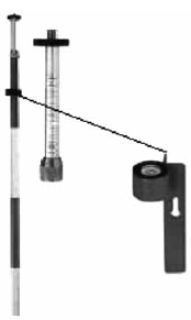
Figure 26.10 Typical standard rod (w/bubble level)

Figure 26.11 Typical standard prism and sight
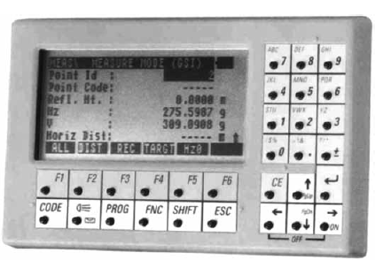
Figure 26.12 Display (Leica)
26.2.2.1 Advantages of total station
- Quick setting of the instrument on the tripod using laser plummet.
- On board area computation program will compute the area of the field and the area computation is more accurate.
- Graphical view of plots and land for quick visualization.
- As soon as the field jobs are finished, the map of the area with dimension is ready after data transfer.
- Enormous plotting and area computation at any user required scale.
- Integration of database (Exporting Map to GIS packages).
- Automation of old maps.
26.2.3 Global positioning system (GPS)
GPS is a satellite navigation system designed to provide instantaneous position, velocity and time information almost anywhere on the globe at any time and in any weather (Figure 26.13).
Present usage of GPS for positioning includes personal navigation (hiking, boating, hunting, driving directions, etc.), aircraft navigation, offshore survey and vessel navigation, fleet tracking, dredging, machine control, civil engineering, land surveying, GIS and mapping, deformation analysis, etc. The list is almost endless.
The day-to-day running of the GPS program and operation of the system rests with the US Department of Defense (DoD). Originally designed by the US Department of Defense (DoD), GPS comprises three main components: the control segment, the space segment and the user segment. Nowadays, GPS is used for topographic surveys and hydrographic surveys. The survey grade GPS receivers can achieve 2 mm accuracy for horizontal measurements and upto 5 mm accuracy for vertical measurements.
The control segments are stations situated on the ground on various parts of the world. These are the eyes and ears of the GPS and they keep tracking the satellites, which are rotating around the earth in various orbits in space at a height of 20,183 km above the earth. There are at present 24 such satellites, and they constitute the space segment.
The user segment comprises the receivers that have been designed to decode the signals transmitted from the satellites for the purposes of determining position, velocity or time. To compute the positional value from GPS satellite signals, a GPS receiver must perform the following tasks.
- Selecting one or more satellites in view
- Acquiring GPS signals
- Measuring and tracking
- Recovering navigational data
- Calculation of the positional value
26.2.4 Automatic level
Automatic levels are extremely popular in present-day surveying operations and are very easy to be set up and can be used with any amount of precision.

Figure 26.13 GPS and receiver (courtesy M/s. Sokkia and M/s. Leica)
They can be simply mounted on a tripod and can be set up and the circular bubble brought to the centre easily even on an angled and uneven surface. The instrument is equipped with an automatic compensator which is wire suspended and magnetically damped, which makes it suitable even under unstable conditions. Automatic focusing and weather proof telescope makes it useful even under unfavourable weather conditions (Figure 26.14).

Figure 26.14 Automatic level (Pentax)
26.2.5 Digital level
Figures 26.15 and 26.16 show a digital level and a bar code levelling staff. This level features digital, electronic image processing for determining heights and distances, with the automatic recording of data for later transfer to the computer. The digital level is an automatic level (pendulum compensator) capable of normal optical levelling with rod graduated in feet or metres. When used in electronic mode, with the rod face graduated in barcode, this level will, with the press of a button, capture and process the image of the bar-code rod. This processed image of the rod reading is then compared with the image of the whole rod, which is stored permanently in the level’s memory module, to determine height and distance values (Figures 26.15 and 26.16).
After the instrument has been levelled the operator must focus the image of the barcode properly. Next, the operator presses the measure button to begin the image processing, which takes about 4 seconds. Although the heights and distances are automatically determined and recorded, the horizontal angles must be read and recorded manually in this case. All the readings are digitally displayed and recorded for transfer to the computer.
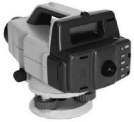
Figure 26.15 A digital level (courtesy of Sokkia corp.)

Figure 26.16 A digital level and bar code staff (courtesy of M/S. Leica geo-systems)
26.2.6 Microptic theodolite
It is a reliable, convenient, highly precise and easy to use instrument used for most surveying tasks including engineering and mining applications. It is equipped with a magnetically damped vertical circle compensator for fast and accurate zenith angle compensation. The optical plummet provided makes it easy to centre the instrument over the survey point with the help of a shifting tribrach. Coincident image projection is used to read the horizontal and vertical scales and thus possibility of any type of error in reading is eliminated. The readings can be directly read looking through the micrometer eye piece, which is illuminated using reflectors.
This instrument can be used in combination with an EDM (Figure 26.17).
26.2.7 Electronic digital theodolite
This functions in the same manner as that of an ordinary transit theodolite, except that it is more accurate, error free and easy to operate. There is an electronic compensator provided, which simplifies the levelling process and improves the accuracy by compensating the faulty adjustments. A laser plummet is provided for accurate centring. Electronic display of all the readings is automatically available. It works on rechargeable batteries.
26.2.8 Digital planimeter
Planimeter is an instrument used to measure the area of irregular shapes. The original version consists of tracing the boundaries with the arm of the planimeter and then converting the obtained reading into area of the figure, using the specified formula. Here, the possibility of error is very high and the procedure is not so easy (Figure 26.18).
Now, digital planimeters which work on rechargeable batteries and directly display the area required are available. These give a more accurate and quick measure of the area and in addition they allow calculations of line lengths, circumference, coordinates, angles, arc and circle radii and many other functions. LCD display, attached printers and computer compatibility are added advantages.

Figure 26.17 Microptic theodolite (Lawrence &Mayo)

Figure 26.18 Digital planimeter (PLACOM KP – 90 N)